From Data to Display: How Computers Present Images14 min read
Most of us use technological devices daily, and they’re an indispensable part of our lives. A few decades ago, when the first computer came up, the screen only displayed black and white colors. Nowadays, from phones to computers to technical devices, the colorful display is what we take for granted. But there is one interesting question from a technical perspective: if the computer can only understand zeros and ones, then how can a colorful image be displayed on our screen? In this blog post, we will try to address this fundamental question and walk through a complete introduction to the image rendering pipeline, from an image stored in memory to being displayed on the screen.
Anatomy of a digital image
Pixels
At the most atomic level, images are constructed by a collection of “pixels”, each pixel is a single point in a digital image and can display exactly one color at a time. When representing a digital image, each pixel corresponds to some “integer coordinate” in the “discrete” space. Simply speaking, we can find out the pixel value at the position like (10, 20) and not (10.1, 20) at a typical 2-dimensional image, and discrete space here means that we have a finite integer space to represent the image, like 1920×1080 pixels (where we have 1920 pixels horizontally — the width, and 1080 pixels vertically — the height).
Formally, we can define how we find a particular value (color) at some particular pixel in 2-dimensional space as follows:
- \(x \in \{0, 1, 2, \ldots, W – 1\} \text{ represents the horizontal position}\)
- \(y \in \{0, 1, 2, \ldots, H – 1\} \text{ represents the vertical position}\)
- \(W \text{ is the width of the image in pixels}\)
- \(H \text{ is the height of the image in pixels}\)
- \(\text{The function } f \text{ maps each coordinate pair } (x, y) \text{ to a color value}\)
Here, \(x, \text{and }y\) must be integers where \(x \in [0, W – 1]\text{ and }y \in[0, H – 1]\). As you try to zoom in on the discrete image at some relatively large size, you can see those little square pixels more clearly. We will then learn about the color format in a pixel once we have all the relevant background.
Physical vs. Logical pixels: A critical distinction
Since different devices have different screen sizes (i.e., in inches) but it doesn’t mean smaller screen devices display fewer pixels than bigger screens. An iPhone has 2556×1179 pixels on the screen, while a standard monitor might have precisely 1920×1080 pixels. And those predefined pixels are actually the physical pixels a screen has, and it cannot be changed. What matters here is the “pixel density per inch”, this can be calculated with the following formula:
\(\large{\text{PPI} = \frac{\sqrt{W^2 + H^2}}{D}}\)- \(\text{W is the number of pixels horizontally (width)}\)
- \(\text{H is the number of pixels vertically (height)}\)
- \(\text{D is the diagonal size of the screen in inches}\)
We’re using the \(\sqrt{W^2 + H^2}\) here because we want to find the diagonal pixel length (finding the hypotenuse value of the right triangle using the Pythagorean theorem) and divide this by the screen size in inches. The higher the value of the PPI, the better the quality of the image and vice versa. However, we also need to note that simply increasing the PPI doesn’t necessarily mean that we can see an image with better quality because human eyes have limitations for visual input.
So what about the logical pixels? This is a software engineering concept that helps maintain consistent sizing across different devices. So, for example, if I have a CSS styling for some button with the width: 44px, this is the logical pixel and not a physical one. Meaning that, depending on the device pixel ratio (DPR), it might be mapped to more physical pixels than the actual logical pixel we’ve given.
For example, if the button has the size of \(44×44\text{pixels}\) and the DPR for a particular device we have is 2x, then the total number of physical pixels for this button on that device will be: \((44*2) * (44*2)\text{pixels}\).
Here is a reference to some common devices with their DPR:
| Device | Screen Size | Resolution | Device Pixel Ratio (DPR) |
| iPhone 15 Pro | 6.1″ | 2556×1179 | 3× |
| MacBook Air (Retina) | 13.3″ | 2560×1600 | 2× |
| iPad Pro | 12.9″ | 2732×2048 | 2× |
| 4K Monitor | 27″ | 3840×2160 | 1.5×-2× (OS dependent) |
Image Dimension, Resolution, and Aspect Ratio
So, let’s talk about another fundamental property of the image, dimensions. This tells us how many pixels it contains horizontally — width, and vertically — height (in this order). For example, images can have many different dimensions such as 512×512, 1920×1080, 1280×720, etc…Some of this can be super familiar, as we often see videos on Youtube or video streaming platforms, to change the video quality we often can choose different options from HD (high-definition) to something better than like 1080p or 4K for example. Those terms represents the absolute pixel resolution, meaning how many total pixels displayed on an image or a video frame, here is the summary table of common classifications with their resolutions:
| Term | Resolution (Width x Height) |
| HD | 1280 x 720 |
| Full HD | 1920 x 1080 |
| QHD | 2560 x 1440 |
| 4K UHD | 3840 x 2160 |
Higher the resolution, the better quality of the image. However, it also comes with a cost, as we can see, when the resolution of the image increased, the more pixels we have, let’s take 1920×1080 resolution for example, if we multiple the dimensions together, there are 2 073 600 pixels to present and store this image, and we haven’t discussed the size of the pixel yet, so let’s presume each pixel takes 1 bytes (8-bit), then we would need around ~2MB to store this still image.
Some common ratio numbers that we also often hear are worth mentioning here, such as 4:3 or 16:9, etc…In the computer graphics work,d it’s called the aspect ratio, the ratio \(\textit{r}\) is calculated by dividing the width dimension to the height dimension: \(\large{r = \frac{W}{H}}\)
The Color of Science
The RGB color model
We already talked at the beginning that computers only understand binary numbers, i.e., 0 and 1, and there is nothing representing color in this understanding, while the fact that colors are something that we as humans perceive — the brain’s interpretation of different wavelengths of light. When color information needs to be stored in computers, we need a precise numerical presentation of colors that we perceive in the language that computers understand.
That’s why the color models come into play; there are many of them, and the most common one is the RGB (Red, Green, Blue) color model. Why choose these particular colors instead of some other colors? It would take a whole blog post to explain the science over here, but to put it succinctly, those colors mimic how the human eye perceives color from different wavelengths of light.
In RGB, each color is a combination of red, green, and blue intensity values. Where each color can be expressed as a tuple \(\textit{(r, g, b)}\), each of the element in this tuple is called a “color component“, where each color component typically ranges from 0 (none) to 255 (maximum intensity) in 8-bit systems.
In this context, each pixel represents a color from the RGB color model. For each color component of this model, we would need \(2^8\text{ bits = 1 byte}\), so totally we need 3 bytes to represent a pixel for this model. The number of possible colors that we can choose from this model is the total permutations we have on those 3 color components: \(256 * 256 * 256 =\text{ 1 6777 216 different colors}\).
What we can say about this is that the number of colors is enough for us for most of the use cases, but in some professional displays or professional editing, more bits per color component might be needed.
Hexadecimal Notation in Web Development
If you have worked with CSS (the language for styling the HTML page), the RGB is commonly represented using hexadecimal notation. Each hex color code begins with a # followed by six hexadecimal digits, where:
- The first two digits represent the red component
- The middle two digits represent the green component
- The last two digits represent the blue component
For example, #FF0000 represents pure red \((255, 0, 0)\). This notation provides a compact way to represent 24-bit RGB colors as text. Each hexadecimal digit represents 4 bits, so 2 digits can represent an 8-bit value (from 00 to FF, corresponding to 0 to 255 in decimal).
Other common color models
There are other common color models as well such as HSL (Hue, Saturation, Lightness) and HSV (Hue, Saturation, Value) reorganize the RGB color space to be more intuitive for human color selection. In these models:
- Hue represents the color type (red, yellow, green, etc), measured in degrees (\(0-360\) degrees)
- Saturation represents color intensity (0% for grayscale, 100% for full color)
- Lightness/Value represents lightness (0% is black, 100% is white or maximum brightness)
There is a formula for the conversion between HSL to RGB, but we won’t go into the details here.
From memory to screen
Now we have enough background knowledge to explore the most interesting part, how the image stored in the computer memory can be rendered and displayed on the screen. There are many steps involved in between, let’s dissect the graphic pipeline — the sequence of steps that transform stored data in computer memory to visible pixels on the screen.
Memory representation of an image
From the lowest level, images in computer memory are just an array of numerical values. For a standard RGB image with 8 bits each color channel, thereare 24 bits for each pixel arranged sequentially, and the memory layout follows one of the two main memory patterns:
- Planar format: All red values, then all green values, and then all blue values.
- Interleaved format: RGB values alternating for each pixel (more common)
To make these description more rigorous, let’s define:
- \(W\text{ is the width of the image in pixels}\)
- \(H\text{ is the height of the image in pixels}\)
- \(N = W * H:\text{total number of pixels in the image}\)
- \(RGB \in [0,255]^3:\text{8-bit color values per channel}\)
In planar format, each pixel of data is stored in three contiguous blocks, one for each color channel:
\(\text{Memory Layout =} [R_{00}, R_{01}, R_{02},\dots,R_{H – 1, W – 1},G_{00}, G_{01},\dots,G_{H-1, W-1},B_{00},B_{01},\dots, B_{H-1,W-1}…B_{H-1,W-1}]\).
In interleaved format, for each pixel, one bit of each color channel is taken, moving to the next bit position and repeating the process (something like RGBRGBRGB….):
\(\text{Memory Layout} = [R_{00}, G_{00}, B_{00},\; R_{01}, G_{01}, B_{01},\; \dots,\; R_{H-1,W-1}, G_{H-1,W-1}, B_{H-1,W-1}]\)We’re consistently saying that for each of the pixel coordinates in discrete space, we have the \((x, y)\) coordinates where the x-value represents the width position on the x-axis while the y-value represents the height position on the y-axis. However, in programming and memory layout, we access the data value by H (row) before the W (column), (e.g, \(array[y][x] \rightarrow\text{ row y, column x}\)).
For a WxH image in the interleaved format, the memory address of the pixel at the coordinate \((x, y)\) can be calculated as:
\(\text{Address} = \text{BaseAddress} + (y \times W + x) \times \text{BytesPerPixel}\\\)The \(BaseAddress\) is the address that we start to search the pixel from, the \(y \times W\) will take us to the correct row while the \(+x\) will lead us to the column position, and we need to multiple with the \(BytesPerPixel\), bringing us to the final memory location of the pixel coordinate.
One important note here is that the (x,y) coordinate is located differently from the mathematical convention; in computer graphics, the y-axis increases as you move down, meaning that, the first row will be in the topmost position while the final row will be in the bottom.
The Role of the GPU
Modern computer graphics relies heavily on specialized hardware — the Graphics Processing Unit (GPU). Unlike the general-purpose CPU, the GPUs are designed for the parallel processing of visual data.
The GPU architecture includes:
- Shader processors: Programmable units that perform calculations on vertices and pixels.
- Texture units: Specialized for sampling and filtering data.
- Rasterizers: Convert vector primitives into pixel fragments.
- ROPs (Render Output Unit): Perform the final pixel operation before displaying
The GPU’s advantage comes from a massive parallel architecture — the modern GPU can have thousands of processing cores that can simultaneously manipulate different pixels.
Frame buffer and display refresh
Interestingly, the image before being displayed on the screen is stored in the frame buffer, most systems would use a double or triple-frame buffer to avoid tearing artifacts. This is because if we just have one buffer, the image is displayed on the screen (reading), but also the buffer holds this image also being rendered (writing) concurrently! As a result, potentially 2 incomplete frames are displayed at the same time. As I’ve been working on Jen — generative art software, we also use double buffering, one for reading and one for writing. This technique helps us separate read from write, creating a smoother user experience. Technically, the processing for rendering and displaying on 2 buffers is:
- While the front buffer (read buffer) is being displayed, the GPU draws the next frame into the back buffer (write buffer).
- Once rendering finishes, the buffers are swapped or flipped.
- The back buffer becomes the new front buffer and vice versa.
Display technologies
Here comes our final component, the displaying technologies! This is the final step in the graphic displaying pipeline. Different technologies have different standards and mechanisms to convert the electrical signals to visible lights that we see on the computer.
LCD (Liquid Crystal Display)
The science behind LCD received the Nobel Prize in 2014. LCD display works by selectively filtering the backlight through liquid crystal system, where each pixel consists of:
- A back light source (LED)
- Polarizing filters: where light is passed through a pair of polarizers, and the crystals determine whether light will be transmitted.
- Liquid crystal layer: controls the polarization of light when a voltage is applied
- Color filters: each pixel is divided into sub-pixels (Red, Green, Blue) that filter the white light into colors.
To have a better sense of it, we can walk through the core mechanism of how LCDs work:
- The GPU sends the RGB values for each pixel to the display controller — often an integrated hardware component that acts as a bridge between image memory (framebuffer) and final physical display panel, where some of the physical interface of this component is commonly heard, such as HDMI/VGA or DSI.
- The controller sends voltages to the liquid crystals to rotate the light polarization.
- Polarizers and color filters selectively select or block the light.
- The viewer sees the colored light intensity per pixel, determined by the crystal alignment.
That’s all! We have learned quite a lot of computer graphics stuff today, from the atomic component of an image, the image dimension, to different color models to the whole rendering pipeline on how the image can be displayed on the screen!
Jen – Generative Photography Software
It’s a great joy that if we have a chance to learn these interesting concepts and know more about the technical details, that makes us feel curious about how this would work. However, it’s even greater when we can apply what we’ve learned so far into the practice. This is exactly what I’m doing with Jen, and you can too! This is an OSS for Generative Photography software where we can apply many different functions and effects on different images and make the patterns follow some interesting mathematical properties!
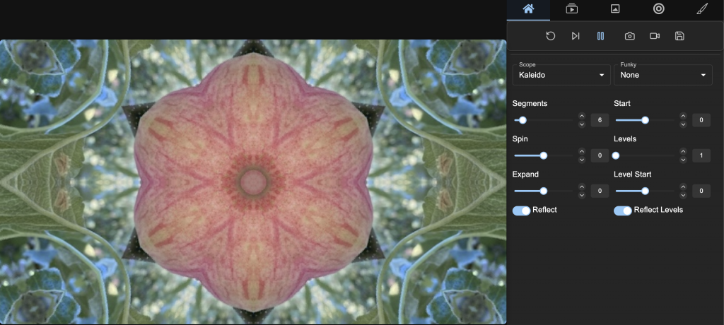
Jen – Generative Photography, Cellular Automata Software